Mounting the thermal imaging module on the adapter
Recommendations for using the PSP B adapter
Legal compliances and disclaimers
Description
Ring Adapters PSP-42B, PSP-50B and PSP-56B are designed to mount Krypton and Proton devices on the lenses of various daylight devices.
The bayonet connection allows you to quickly mount and remove the thermal imaging module from the adapter.
The precise positioning mechanism enables the perfect alignment of a thermal imaging or night image in the field of view of daylight optics to achieve maximum viewing comfort.
Package contents
PSP B Ring Adapter
Allen keys (S2, S4)
Inserts
User manual
Warranty card
Double-sided tape
Mounting the adapter on the device
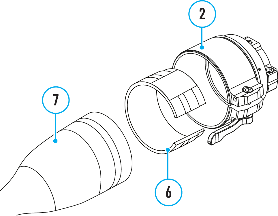
Step 1. Pick up an insert
1. Select the Ring Adapter (2) with the insert (6) of the desired diameter depending on the outer diameter of the lens of your optical device (7).
2. The designation 42 mm / 50 mm / 56 mm in the name of the adapter means the lens diameter of the optical device.
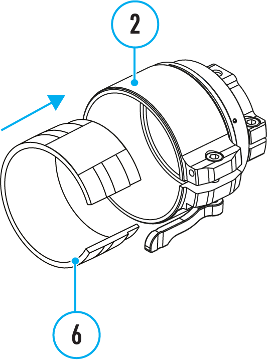
Step 2. Install the insert into the adapter
1. Apply 2-3 strips of double-sided tape to the outer surface of the insert of your choice (6).
2. Push the insert (6) of your choice into the Ring Adapter (2) until it stops.
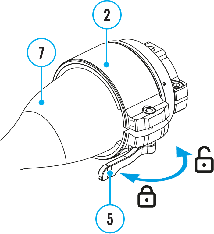
Step 3. Mount the adapter on the optical device
1. Move the lever (5) to the OPEN position .
2. Before installing the Ring Adapter (2) onto the optical device, it is recommended to degrease the lens body of the optical device (7).
3. Mount the Ring Adapter (2) with the insert (6) onto the lens of the daylight optical device (7) as far as it will go.
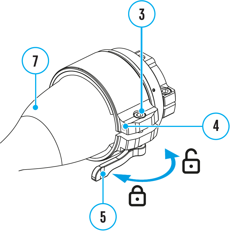
Step 4. Adjust adapter lever
1. Move the lever (5) from its initial OPEN position to the CLOSE .
2. Loosen the locking screw (4) with a 2mm Allen key.
3. Tighten the screw (3) with an Allen key (S = 4mm). The clamping force should be 1.5-2 Nm (13.3-17.7 in-lbs) (use a torque screwdriver) to ensure the lever (5) is correctly tightened, while the Ring Adapter should not move relative to the body of the optical device (7). If necessary, tighten or loosen the screw (3) to operate the lever (5) in the best way possible.
4. Tighten the locking screw (4) as far as it will go
Selection table for optical device inserts
Ring Adapter model
The internal diameter of the insert needs to match the outer diameter of the objective lens housing of the daylight optical device it is being installed on.
Insert internal diameter, mm
Suitable for lens housing of daylight optical devices with an outer diameter of, mm
PSP 42B
(SKU 79206)
45.5
45.5
46
46
46.5
46.5
47
46.7-47.6
48
47.7-48.6
49
48.7-49.6
50
49.7-50.6
PSP 50B
(SKU 79207)
51.6
51.6
53.4
53.4
55
54.7-55.6
56
55.7-56.6
57
56.7-57.6
58
57.7-58.6
59
58.7-59.6
PSP 56B
(SKU 79208)
60
59.7-60.6
61
60.7-61.6
62
61.7-62.6
63
62.7-63.6
64
63.7-64.6
65
64.7-65.6
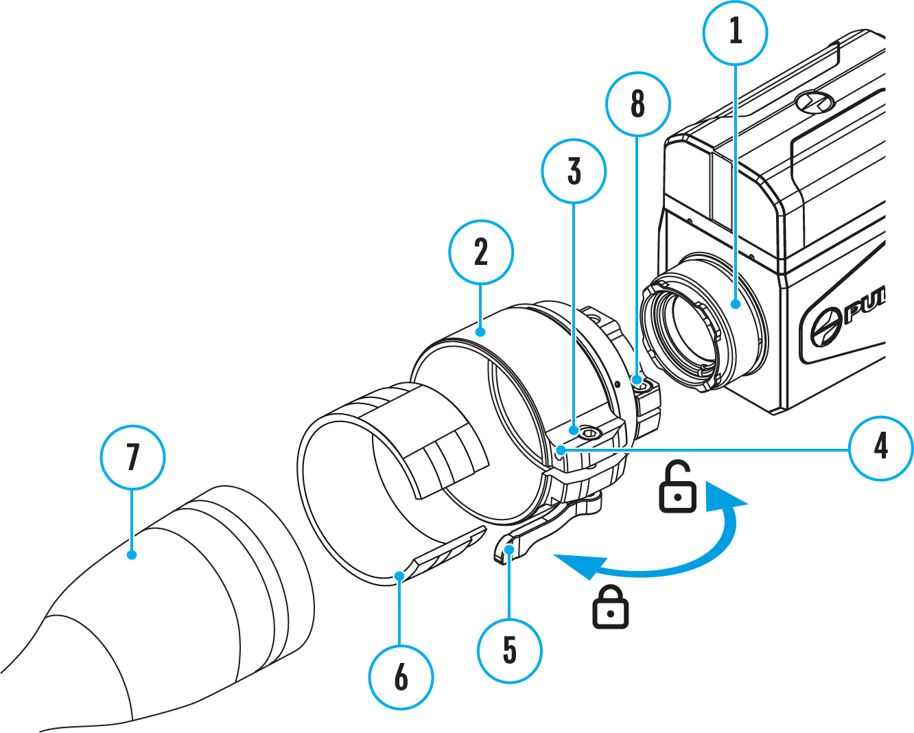
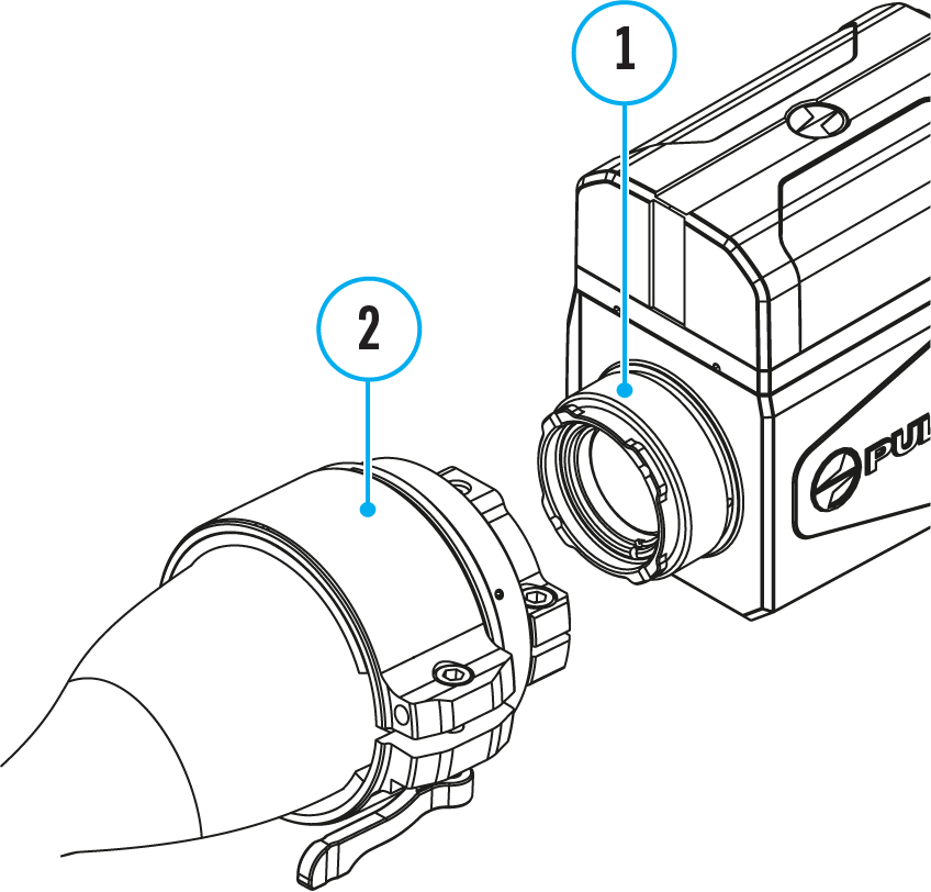
Mounting the thermal imaging module on the adapter
Step 1. Mount the thermal imaging module on the adapter
1. Remove the protective cover from the eyepiece of the thermal imaging module.
2. Align the protrusions on the adapter (2) with the grooves of the mount assembly (1) of the thermal imaging module and turn the thermal imaging module counterclockwise as far as it will go.
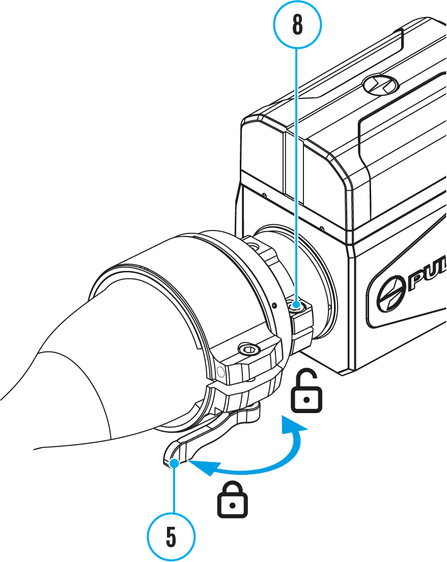
Step 2. Adjust the display position of the thermal imaging module
1. Loosen the screw (8) with an Allen key (S = 4mm).
2. Turn on the thermal imaging module.
3. Align the image center on the display with the image center of the optical device by tilting the thermal imaging module.
4. Tighten the screw (8) as far as it will go. The clamping force should be 5 N·m (44.3 in-lbs) (use the torque screwdriver to check).
5. Move the lever (5) to the OPEN position .
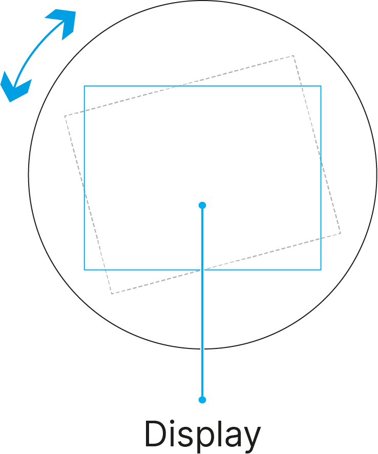
6. Align top and bottom display boundaries parallel to the horizontal axis by turning the adapter with thermal imaging module clockwise or counterclockwise.
7. Move the lever (5) to the CLOSE position .
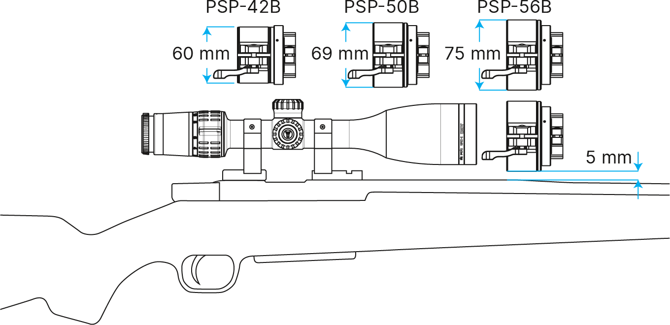
Recommendations for using the PSP B adapter
When installing the PSP B Ring Adapter on the riflescope, the gap between the adapter and the rifle body must be at least 5 mm.
If the gap is insufficient, use higher rings to mount the riflescope.
Legal compliances and disclaimers
Updates of the Product. The manufacturer reserves the right at any time, without mandatory prior notice to the Customer, to make changes to the package contents (subject to the applicable laws, if any), design and characteristics that do not impair the quality of the Product.
Limitation of Liability. Subject to mandatory applicable laws and regulations: manufacturer will not be liable for any claims, actions, suits, proceedings, costs, expenses, damages or liabilities (if any), arising out of the use of this product. Operation and use of the product are the sole responsibility of the Customer. Manufacturer’s sole undertaking is limited to providing the product(s) and related services in accordance with the terms and conditions of concluded transactions, including provisions established in warranty. The provision of products sold and services performed by Manufacturer to the Customer shall not be interpreted, construed, or regarded, either expressly or implied, as being for the benefit of or creating any obligation toward any third party (other than Distributor, Dealer, Buyer). Manufacturer’s liability hereunder for damages, regardless of the form or action, shall not exceed the fees or other charges paid to Manufacturer for the product(s) and/or service(s).
MANUFACTURER WILL NOT BE LIABLE FOR LOST REVENUES OR INDIRECT, SPECIAL, INCIDENTAL, CONSEQUENTIAL, EXEMPLARY, OR PUNITIVE DAMAGES, EVEN IF THE MANUFACTURER KNEW OR SHOULD HAVE KNOWN THAT SUCH DAMAGES WERE POSSIBLE AND EVEN IF DIRECT DAMAGES DO NOT SATISFY A REMEDY.